- Cooling channels
- Heat-exchanger passages
- Microchannels
- Thermal-management manifolds
Application Domain 05
Heat Exchangers & Cooling Channels
Researching coupled flow and heat-transfer behavior in governed thermal surfaces.
Research-stage application · performance validation pending
Application Thesis
A governed architecture—not a universal surface treatment.
DDM treats cell geometry, spacing, orientation, density, and placement as application-dependent variables. Candidate configurations must be tuned to the local flow regime, surface geometry, operating envelope, materials, and performance objective.
Public descriptions communicate the research hypothesis and validation strategy. Detailed geometry ranges, configuration logic, and application-specific design rules remain controlled technical information.
Complete Visual Reference
View the full application overview sheet.
The complete sheet brings the application regions, candidate outcomes, flow mechanisms, design variables, materials, integration paths, and validation roadmap together in one technical visual.
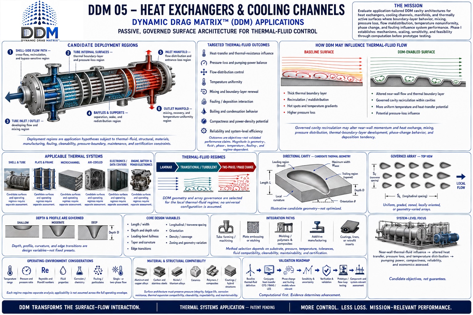 Click the sheet to open the full-resolution view ↗
Potential if Validated
Better thermal transport can unlock capacity, efficiency, compactness, and reliability.
DDM is investigating whether governed channel and exchanger surfaces can influence the hydrodynamic and thermal boundary layers together—improving near-wall transport, flow distribution, pressure recovery, temperature uniformity, and fouling behavior. The central challenge is not maximizing turbulence; it is improving useful heat transfer without imposing a larger hydraulic, acoustic, structural, or maintenance penalty.
Govern coupled transport
Test velocity and temperature fields, near-wall mixing, thermal resistance, separation, recirculation, deposition, boiling, and condensation behavior.
Improve verified duty
Measure heat duty, overall conductance, effectiveness, pressure drop, pumping or fan power, temperature uniformity, fouling rate, and off-design penalties.
Translate the result
Convert validated system changes into capacity, footprint, electrical demand, process throughput, component temperature, maintenance intervals, uptime, and lifecycle cost.
Where DDM Could Apply
From industrial exchangers to microscopic cooling passages.
Each platform requires its own geometry, materials, cleaning strategy, pressure boundary, and validation program. This page focuses on surfaces whose purpose is thermal transport; fluid-delivery networks remain in Pipes, Ducts & Pump Intakes.
Industrial process systems
Shell-and-tube, plate-and-frame, spiral, welded-plate, and process coolers handling demanding temperatures, pressures, chemistries, and duty cycles.
HVAC & refrigeration
Evaporators, condensers, chilled-water loops, air coils, intercoolers, and recovery systems where capacity, fan or pump power, and fouling interact.
Data centers & electronics
Cold plates, cooling-distribution units, rear-door exchangers, microchannels, immersion loops, and high-heat-flux power-electronics cooling.
EVs, batteries & mobility
Battery plates, inverter and motor cooling, radiator passages, oil coolers, and compact thermal systems constrained by weight, volume, and pumping power.
Aerospace & defense
Fuel, oil, air, avionics, environmental-control, and mission-system exchangers where thermal performance must coexist with mass, pressure, vibration, and reliability limits.
Power, cryogenic & two-phase
Boilers, condensers, recuperators, fuel cells, cryocoolers, evaporating and condensing channels, and other phase-change-sensitive systems.
Representative Deployment Zones
Treat the thermal bottleneck—not every wetted surface.
- A
Primary heat-transfer surfacesPlate channels, tube interiors, cold plates, jackets, and passages where near-wall thermal resistance governs duty.
- B
Inlets and distribution regionsHeaders, ports, manifolds, and entrance zones controlling maldistribution, inactive area, and local hot spots.
- C
Turns, baffles, and transitionsSeparation, secondary flow, bypass, pressure recovery, mixing, vibration, and erosion-sensitive locations.
- D
Air-side fins and passagesCoils, radiators, intercoolers, and condensers challenged by dust, insects, moisture, icing, noise, and cleaning access.
- E
Phase-change and high-flux zonesEvaporating, condensing, boiling, cryogenic, and electronics-cooling surfaces requiring stability and critical-heat-flux evidence.
Engineering Translation
Heat duty depends on conductance and temperature driving force; pumping power depends on flow, pressure rise, and efficiency.
A higher local heat-transfer coefficient does not automatically produce the same percentage increase in exchanger duty, and a lower component pressure drop does not automatically produce the same percentage energy saving. Both effects must be propagated through the complete thermal and hydraulic system.
Illustrative Thermal-Capacity Lens
What a validated exchanger-level duty improvement could mean.
For a heat exchanger transferring 5 MW at a defined pair of inlet conditions and flow rates, a verified 5%, 10%, or 20% increase in duty would correspond to an additional 0.25 MW, 0.50 MW, or 1.0 MW of thermal transfer. This assumes the stated operating boundary remains valid; it is not a prediction of DDM performance or proof that the existing system can use the additional capacity.
+5%+0.25 MW thermal duty
+10%+0.50 MW thermal duty
+20%+1.0 MW thermal duty
Illustrative Energy Opportunity
What system-level electrical improvement could mean.
Assumed operating case: 5 GWh of annual pumping, fan, and cooling electricity at an illustrative $0.10/kWh. A 20-exchanger facility is shown for scale. These are conditional calculations—not measured DDM results, a utility-price forecast, or a guarantee of facility-level savings.
Conservative threshold
2%
system-level electrical improvement
- Electricity avoided annually
- 100,000 kWh
- Annual value per system
- $10,000
- 20-system annual value
- $200,000
Target threshold
5%
system-level electrical improvement
- Electricity avoided annually
- 250,000 kWh
- Annual value per system
- $25,000
- 20-system annual value
- $500,000
High-impact threshold
10%
system-level electrical improvement
- Electricity avoided annually
- 500,000 kWh
- Annual value per system
- $50,000
- 20-system annual value
- $1 million
Uniformity, Fouling & Reliability Opportunity
A more uniform temperature field may protect the asset as well as the energy budget.
If testing demonstrates reduced maldistribution, wall-temperature variation, deposition, or pressure fluctuation, the resulting value could include fewer hot spots, higher allowable power density, slower performance degradation, longer cleaning intervals, lower thermal stress, and greater uptime. Those consequences require endurance data, surface inspection, mass-balance or fouling measurements, and component-level reliability evidence.
ΔTtemperature spread and hot-spot control
ΔPpressure loss across the tested duty range
Rffouling resistance versus time
The DDM Validation Gate
Thermal gains must survive the complete heat-and-flow balance.
DDM must demonstrate repeatable local transport effects, then quantify exchanger and system performance across Reynolds and Prandtl regimes, heat flux, wall and bulk temperature, viscosity, conductivity, flow rate, pressure, channel geometry, fluid chemistry, phase change, fouling, scaling, corrosion, erosion, cleaning, manufacturing tolerance, thermal cycling, and off-design operation. Testing must compare equal boundary conditions and report both thermal benefit and hydraulic cost.
Authoritative Benchmarks & Calculation Basis
DOE — Energy-Efficient Data-Center DesignDOE identifies liquid cooling, close-coupled heat exchangers, pump and fan optimization, thermal monitoring, and total-cost metrics as connected parts of efficient cooling-system design.Open official source ↗DOE — Centrifugal-Pump Energy TranslationDOE calculates pumping energy from operating head, flow, efficiency, motor efficiency, and annual hours—supporting system-level measurement rather than a pressure-drop claim in isolation.Open official source ↗NIST — Cooling-Coil FoulingNIST evaluates the effect of fouling through heat-exchanger effectiveness and NTU across operating states, underscoring that fouling consequences change with the system condition.Open official source ↗NASA — Thermal-Management DesignNASA describes thermal-management design as meeting component temperature limits while minimizing power, weight, and drag—the same coupled trade space DDM must ultimately validate.Open official source ↗
Thermal-capacity arithmetic: 5 MW baseline duty × modeled exchanger improvement. Energy arithmetic: 5 GWh annual electrical baseline × modeled system improvement; economic value uses $0.10/kWh. All percentages are DDM research thresholds, not achieved performance.
Research Questions
What must be established before performance can be claimed.
Can local recirculation improve thermal uniformity without excessive pressure loss?
How do geometry and array organization change heat-transfer and pumping-power tradeoffs?
What fouling and manufacturability limits govern deployment?
Validation Path
From application hypothesis to defensible evidence.
- 01
Establish conjugate heat-transfer baselines
- 02
Map thermal and hydraulic trade spaces
- 03
Assess fouling and manufacturability
- 04
Validate supported designs in thermal-flow rigs
Evidence status
No application-specific performance figures are presented here as demonstrated results. Quantitative claims will be published only when supported by traceable computational or experimental evidence and clearly stated boundary conditions.
Application-Specific Collaboration
Evaluate alignment with this research domain.
DDM welcomes conversations with government programs, laboratories, universities, OEMs, and technical partners.
Discuss this application