- Bow, mid-hull, stern, and wake-sensitive zones
- Hydrofoils, control foils, struts, and keels
- Sonar domes, rudders, stabilizers, and appendages
- Waterjet tunnels, pump intakes, and propulsor-inflow regions
- Submarine, ROV, AUV, and submersible skins
Application Domain 02
Marine Hulls & Hydrofoils
Investigating governed hydrodynamic surfaces for lower resistance, greater endurance, quieter operation, and improved foil performance.
Research-stage application · performance validation pending
Application Thesis
A governed architecture—not a universal surface treatment.
DDM treats cell geometry, spacing, orientation, density, and placement as application-dependent variables. Candidate configurations must be tuned to the local flow regime, surface geometry, operating envelope, materials, and performance objective.
Public descriptions communicate the research hypothesis and validation strategy. Detailed geometry ranges, configuration logic, and application-specific design rules remain controlled technical information.
Complete Visual Reference
View the full application overview sheet.
The complete sheet brings the application regions, candidate outcomes, flow mechanisms, design variables, materials, integration paths, and validation roadmap together in one technical visual.
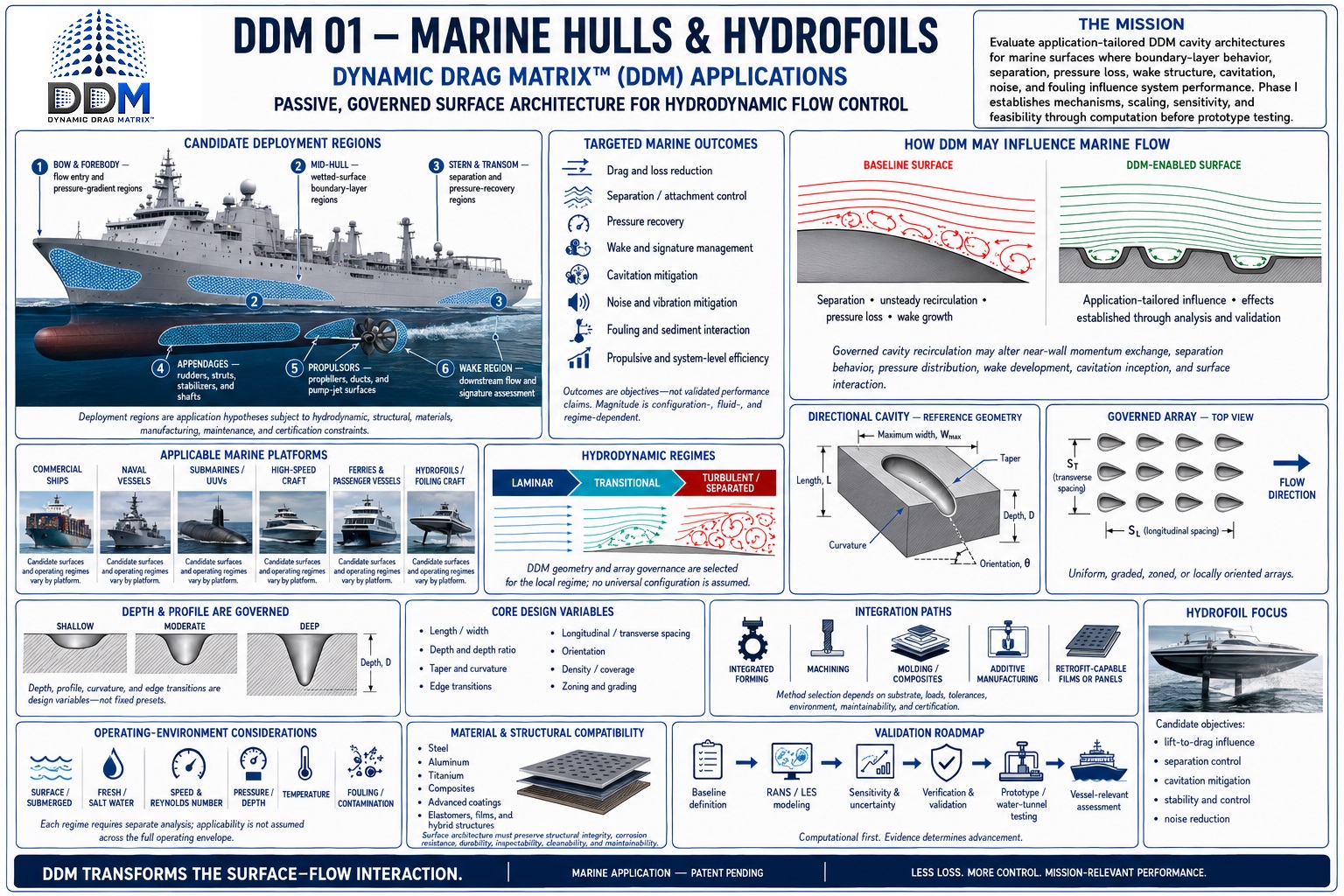 Click the sheet to open the full-resolution view ↗
Potential if Validated
Less resistance can mean more range, endurance, and mission capability.
DDM is investigating whether locally governed geometry can influence skin friction, separation, pressure recovery, wake structure, cavitation behavior, and flow-induced noise. Marine value will depend on where those effects occur, how they scale, and whether they persist through fouling, erosion, coatings, waves, and changing operating conditions.
Govern local water flow
Test attachment, near-wall recirculation, pressure gradients, cavitation inception, and wake development at selected hull and foil zones.
Reduce verified losses
Quantify treated-region and whole-vessel resistance, required shaft power, foil lift and stability, acoustic response, and off-design penalties.
Translate the result
Convert validated vessel-level changes into fuel or battery endurance, range, speed margin, emissions, maintenance, comfort, and mission value.
Where DDM Could Apply
One marine architecture. Distinct platform missions.
Each platform requires its own geometry, placement, operating envelope, and validation program. Propeller blades, thrusters, nozzles, and pods form a related but separate Marine Propulsion Systems application.
Commercial ships
Cargo vessels, tankers, container ships, cruise ships, and other high-utilization fleets where small resistance reductions compound across long duty cycles.
Ferries & passenger vessels
Conventional and hydrofoil ferries where fuel cost, wake, ride quality, schedule speed, and passenger comfort converge.
Naval surface combatants
Destroyers, frigates, littoral combat ships, patrol craft, and support vessels with endurance, sonar self-noise, cavitation, and signature constraints.
Submarines & unmanned systems
Submarines, ROVs, AUVs, and other submersibles where hydrodynamic efficiency can translate into range, battery endurance, maneuverability, and acoustic performance.
Hydrofoils & high-speed craft
Passenger hydrofoils, fast-attack craft, racing vessels, and research platforms with lift-critical, cavitation-sensitive foil surfaces.
Sail & renewable marine systems
Keels, rudders, tidal structures, and wave-energy components exposed to changing incidence, fouling, erosion, and multiphase flow.
Representative Deployment Zones
DDM would be zoned—not tiled indiscriminately across a vessel.
- A
Bow regionFlow entry, pressure-gradient management, and separation control.
- B
Mid-hull regionSkin-friction and boundary-layer behavior across large wetted areas.
- C
Stern and inflow regionWake organization, pressure recovery, and cleaner flow into the propulsor.
- D
Foils, struts, and appendagesLift, stall margin, cavitation inception, junction flow, vibration, and control authority.
Illustrative Fleet Opportunity
What verified truck-level fuel improvement could mean.
Assumed operating case: 100 long-haul trucks, each using 20,000 gallons of diesel annually, at an illustrative $4.00 per gallon. These are conditional calculations—not measured DDM results, a diesel-price forecast, or a guarantee of fleet performance.
Conservative threshold
1%
truck-level fuel-use improvement
- Fleet diesel avoided annually
- 20,000 gal
- Illustrative annual value
- $80,000
- Combustion CO₂ avoided
- 204 metric tons
Target threshold
3%
truck-level fuel-use improvement
- Fleet diesel avoided annually
- 60,000 gal
- Illustrative annual value
- $240,000
- Combustion CO₂ avoided
- 613 metric tons
High-impact threshold
5%
truck-level fuel-use improvement
- Fleet diesel avoided annually
- 100,000 gal
- Illustrative annual value
- $400,000
- Combustion CO₂ avoided
- 1,021 metric tons
Illustrative Opportunity Model
What vessel-level efficiency improvement could mean.
Assumed operating case: 5 million gallons of annual marine-diesel use at an illustrative $3.00 per gallon. These are conditional calculations—not measured DDM results, a fuel-price forecast, or a guarantee of vessel-level performance.
Conservative threshold
2%
vessel-level fuel-use improvement
- Fuel avoided annually
- 100,000 gal
- Illustrative annual value
- $300,000
- Combustion CO₂ avoided
- 1,021 metric tons
Target threshold
5%
vessel-level fuel-use improvement
- Fuel avoided annually
- 250,000 gal
- Illustrative annual value
- $750,000
- Combustion CO₂ avoided
- 2,553 metric tons
High-impact threshold
10%
vessel-level fuel-use improvement
- Fuel avoided annually
- 500,000 gal
- Illustrative annual value
- $1.5 million
- Combustion CO₂ avoided
- 5,105 metric tons
Acoustic & Cavitation Opportunity
A quieter flow field can carry commercial and tactical value.
If testing demonstrates a reduction in a defined underwater acoustic measurement at the same operating condition, a 3 dB reduction corresponds to roughly 50% less sound power, 6 dB to 75% less, and 10 dB to 90% less. The effect on crew and passenger comfort, marine life, sonar self-noise, vessel detectability, and certified metrics must be evaluated separately.
−3 dB≈ 50% less sound power
−6 dB≈ 75% less sound power
−10 dB≈ 90% less sound power
The DDM Validation Gate
Marine performance must survive the ocean—not merely a clean laboratory run.
DDM must demonstrate repeatable local-flow improvement, then quantify whole-vessel effects across speed, draft, trim, sea state, Reynolds and Froude regimes, curvature, coating systems, fouling, debris, erosion, aeration, cavitation, and maintenance cycles. A configuration that helps one zone or operating point must not create unacceptable drag, noise, structural, or service penalties elsewhere.
Authoritative Benchmarks & Calculation Basis
U.S. DOE — Maritime R&D OpportunitiesDOE reports that hydrodynamic stern-flap devices may produce power reductions ranging from 4% to 19%, illustrating the leverage available in vessel-flow management.Open official source ↗IMO — Energy-Efficiency TechnologiesIMO identifies reduced hull resistance and lower main-engine load as the central value pathway for drag-reduction technologies such as air lubrication.Open official source ↗U.S. Navy — Hull-Coating ResearchNavy research reports that biofilm can add up to 20% drag and barnacles more than 60%, underscoring the importance of fouling tolerance and full-scale durability.Open official source ↗EPA — Greenhouse-Gas FactorsEPA lists 10.21 kg of combustion CO₂ per gallon of diesel fuel; that factor drives the illustrative emissions calculations below.Open official source ↗
Scenario arithmetic: annual baseline × modeled improvement; economic value uses $3.00/gal; combustion CO₂ uses EPA's 10.21 kg/gal diesel factor and is rounded to the nearest metric ton.
Research Questions
What must be established before performance can be claimed.
Where can local surface governance influence attachment, friction, or wake organization?
How do fouling, roughness, cavitation risk, and seawater exposure constrain viable geometries?
Which effects persist across speed, loading, and scale?
Validation Path
From application hypothesis to defensible evidence.
- 01
Define hydrodynamic baselines
- 02
Evaluate zonal configurations computationally
- 03
Assess cavitation and fouling constraints
- 04
Advance supported candidates to tow-tank or water-tunnel testing
Evidence status
No application-specific performance figures are presented here as demonstrated results. Quantitative claims will be published only when supported by traceable computational or experimental evidence and clearly stated boundary conditions.
Application-Specific Collaboration
Evaluate alignment with this research domain.
DDM welcomes conversations with government programs, laboratories, universities, OEMs, and technical partners.
Discuss this application