- Bridge decks and pylons
- Towers and supports
- Spillways and channels
- Dams and hydraulic structures
Application Domain 07
Civil Structures & Bridges
Investigating governed surfaces for wind- and water-exposed infrastructure.
Research-stage application · performance validation pending
Application Thesis
A governed architecture—not a universal surface treatment.
DDM treats cell geometry, spacing, orientation, density, and placement as application-dependent variables. Candidate configurations must be tuned to the local flow regime, surface geometry, operating envelope, materials, and performance objective.
Public descriptions communicate the research hypothesis and validation strategy. Detailed geometry ranges, configuration logic, and application-specific design rules remain controlled technical information.
Complete Visual Reference
View the full application overview sheet.
The complete sheet brings the application regions, candidate outcomes, flow mechanisms, design variables, materials, integration paths, and validation roadmap together in one technical visual.
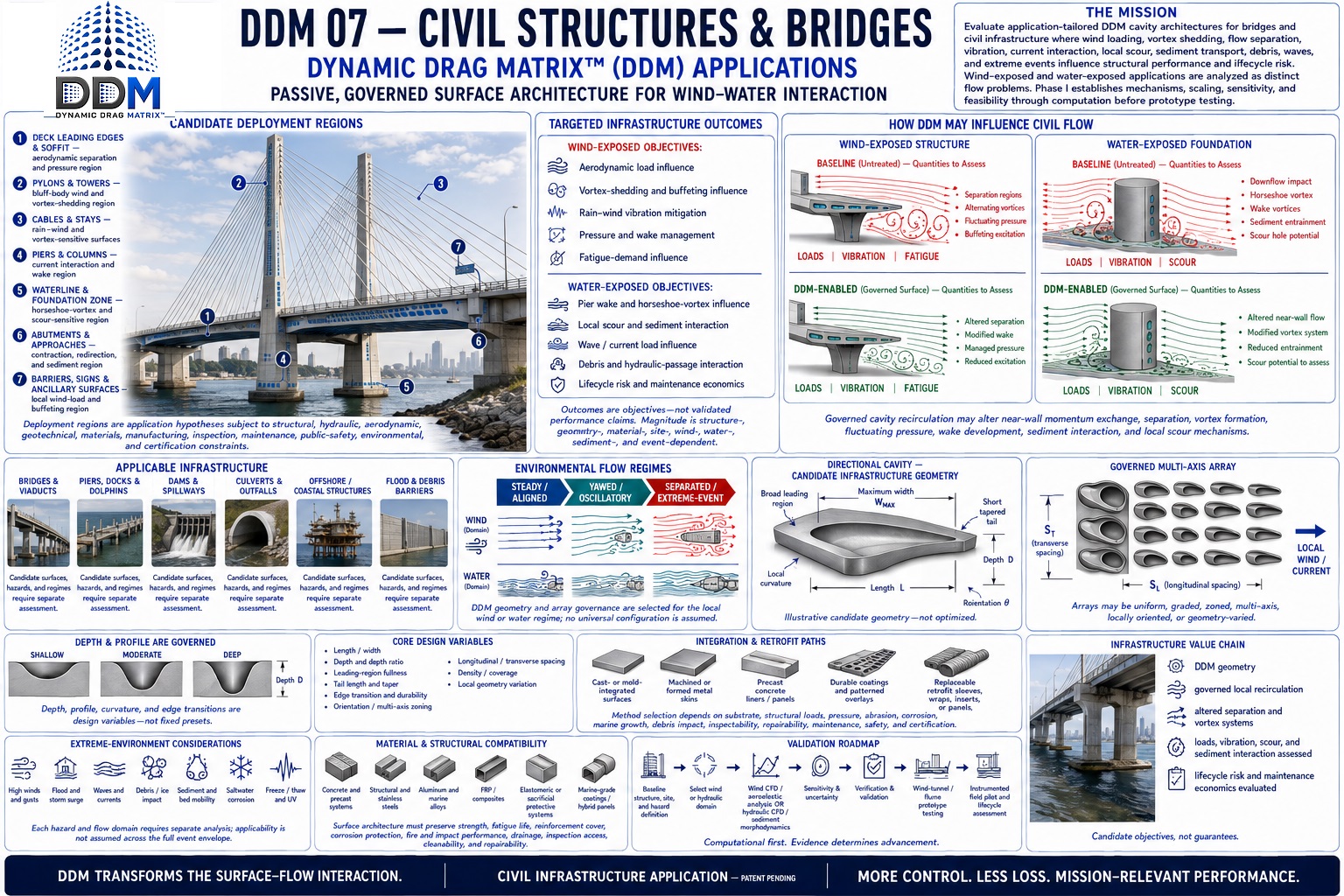 Click the sheet to open the full-resolution view ↗
Potential if Validated
Govern the flow before wind and water become structural damage.
DDM is investigating whether governed surface architectures can alter separation, vortex formation, fluctuating pressure, near-bed downflow, wake structure, and cavitation-sensitive pressure gradients around civil infrastructure. The opportunity spans both fluids—but every bridge, pier, spillway, tower, and offshore structure requires its own load cases, failure modes, and validation program.
Alter the forcing mechanism
Test separation, horseshoe and wake vortices, shedding coherence, pressure fluctuation, cavitation index, near-bed velocity, and turbulent structures.
Reduce verified demand
Measure mean and cyclic force, moment, vibration, scour, erosion, uplift, fatigue spectrum, hydraulic capacity, and extreme-event behavior.
Translate supported results
Convert validated demand changes into safety margin, foundation exposure, inspection, repair scope, downtime, resilience, service life, and lifecycle cost.
Where DDM Could Apply
Infrastructure exposed to wind, water, or both.
DDM would complement—not replace—code-required structural capacity, foundations, armoring, aeration, damping, inspection, and emergency planning. Its role must be established as an application-specific flow-control layer.
Bridges & stay systems
Decks, soffits, pylons, piers, abutments, stay cables, bearings, and approaches exposed to wind, water, rain-wind vibration, scour, and fatigue.
Dams & spillways
Chutes, tunnels, gates, aerators, flip buckets, stilling basins, intake towers, and other high-velocity hydraulic surfaces.
Ports & coastal infrastructure
Piers, docks, pilings, seawalls, flood barriers, storm-surge gates, and navigation structures exposed to waves, currents, sediment, salt, and debris.
Offshore structures
Platform legs, monopiles, jackets, riser guards, subsea frames, and renewable-energy foundations subject to combined waves, currents, wind, and cyclic loading.
Buildings, towers & stacks
High-rise buildings, cooling towers, chimneys, masts, and slender components where separated flow can drive load, sway, vibration, fatigue, and occupant discomfort.
Culverts & flood-control works
Culverts, channels, outfalls, levee penetrations, energy dissipators, and debris-prone conveyance structures operating across extreme events.
Representative Deployment Zones
Target the forcing zones and their downstream consequences.
- A
Bridge decks and soffitsAttachment, flutter derivatives, buffeting, lift, drag, moment, rain, icing, and inspection access.
- B
Piers, columns, and foundationsDownflow, horseshoe vortices, wake shedding, local scour, debris interaction, and flood-stage loading.
- C
Cables, stays, towers, and stacksRain-wind response, vortex-induced vibration, galloping, fatigue, sway, and aerodynamic damping.
- D
Spillways and energy dissipatorsHigh-velocity pressure gradients, cavitation, aeration, uplift, erosion, jet breakup, and downstream protection.
- E
Coastal and offshore membersCombined wave-current loading, marine growth, sediment, salt, corrosion systems, fatigue, and storm conditions.
Engineering Translation
Fluid-force improvement is not automatically structural-life improvement.
Mean load, fluctuating load, frequency content, damping, resonance proximity, stress concentration, cumulative cycles, foundation condition, and extreme-event combinations must be carried through the structural model. DDM must not shift energy into a more damaging frequency or failure mode.
Illustrative Wind/Current Load Lens
What a validated structural-load improvement could mean.
Assumed structural case: a representative exposed component carrying 10 MN of fluid-induced design load. The economic column applies the same percentage to a separate illustrative $10 million repair or strengthening event; it is a sensitivity calculation, not an asserted one-to-one saving.
Conservative threshold
2%
validated load-reduction threshold
- Design-load change
- 0.20 MN
- Equivalent force
- ≈ 45,000 lbf
- $10M event sensitivity
- $200,000
Target threshold
5%
validated load-reduction threshold
- Design-load change
- 0.50 MN
- Equivalent force
- ≈ 112,000 lbf
- $10M event sensitivity
- $500,000
High-impact threshold
10%
validated load-reduction threshold
- Design-load change
- 1.0 MN
- Equivalent force
- ≈ 225,000 lbf
- $10M event sensitivity
- $1 million
Illustrative Scour Lens
Centimeters can matter when foundation embedment is finite.
For a baseline local design-scour depth of 4.0 m, a verified 5%, 10%, or 20% reduction would correspond to 0.20 m, 0.40 m, or 0.80 m less scour. Foundation safety, total-scour estimation, contraction scour, channel migration, debris, sediment gradation, flood duration, and countermeasure performance remain separate design requirements.
5%0.20 m shallower
10%0.40 m shallower
20%0.80 m shallower
Vibration, Cavitation & Fatigue Opportunity
The amplitude alone is not the whole answer.
A lower response amplitude may reduce cyclic stress, but fatigue value depends on the full stress-range distribution and number of cycles. Cavitation value depends on pressure history, surface irregularity, air concentration, material resistance, and exposure duration. Both require application-specific endurance evidence—not a single favorable snapshot.
F(t)mean and fluctuating force
f / ζfrequency and damping
σ / Nstress range and cycles
The DDM Validation Gate
Civil performance must survive scale, decades, and extreme events.
DDM must demonstrate repeatable flow effects, then quantify structural and hydraulic response across Reynolds and Froude regimes, wind yaw and turbulence, wave-current combinations, flood hydrographs, sediment mobility, debris, marine growth, roughness, cavitation, aeration, erosion, corrosion protection, freeze-thaw, UV exposure, construction tolerance, inspection, repair, seismic combinations, and code-governed extreme loads. Validation should progress from CFD and sectional models to hydraulic or wind-tunnel testing, instrumented prototypes, and long-duration field monitoring.
Authoritative Benchmarks & Calculation Basis
FHWA — Bridge AerodynamicsFHWA wind-tunnel research measures mean and fluctuating bridge forces across wind speed, inclination, and yaw—exactly the kind of envelope required before structural value can be claimed.Open official source ↗FHWA — Wind-Induced Cable VibrationFHWA documents that flexible bridges and cable systems move under turbulent wind and distinguishes buffeting from aeroelastic instability, requiring mechanism-specific validation.Open official source ↗Bureau of Reclamation — Cavitation RiskReclamation identifies cavitation as time-dependent and sensitive to pressure change, surface irregularities, air concentration, material durability, and exposure duration.Open official source ↗NIST — Wind Effects on High-Rise StructuresNIST evaluates wind-induced strength and serviceability response in flexible high-rise structures, reinforcing the need to measure both load and dynamic behavior.Open official source ↗
Load arithmetic: 10 MN baseline × modeled improvement. Event-value arithmetic: $10 million × the same sensitivity percentage, shown only as an economic lens. Scour arithmetic: 4.0 m baseline × modeled improvement. All percentages are DDM research thresholds, not achieved performance.
Research Questions
What must be established before performance can be claimed.
Can surface governance alter separation, vortex shedding, or localized hydraulic behavior?
Which effects remain meaningful at civil scale?
How do durability, inspection, debris, and retrofit constraints shape deployment?
Validation Path
From application hypothesis to defensible evidence.
- 01
Define structural and fluid baselines
- 02
Model application-specific surface zones
- 03
Assess scale and durability constraints
- 04
Validate with sectional or hydraulic models
Evidence status
No application-specific performance figures are presented here as demonstrated results. Quantitative claims will be published only when supported by traceable computational or experimental evidence and clearly stated boundary conditions.
Application-Specific Collaboration
Evaluate alignment with this research domain.
DDM welcomes conversations with government programs, laboratories, universities, OEMs, and technical partners.
Discuss this application